Start with the geometry
nDisplay coordinates Unreal instances and maps their rendered views to physical screens or projectors. Its configuration records display geometry, render nodes, and viewport assignments. It is not simply a way to stretch a desktop across a large display. The virtual layout has to describe the physical arrangement closely enough for the intended view to work.
Source: nDisplay Overview
The inner frustum is a specific workload
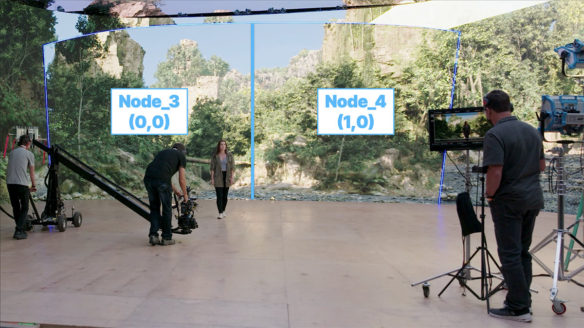
For an ICVFX camera, the inner frustum is the camera-oriented view used within the surrounding wall imagery. Epic documents configurations that distribute this work across nodes using SMPTE 2110. The annotated stage image above shows that particular split workflow. It does not mean a beginner’s setup requires the same network or number of machines.
Source: Configuring an Inner Frustum Split
What to ask during a stage visit
Atlas checklist
Ask the operator to show the approved camera range, not only a beautiful static frame. See what happens as the camera reaches its intended extremes and as the lens changes. A diagram of the room is useful; a test with the actual camera path is more revealing.
Separate a geometry problem from a speed problem. Adding render hardware does not by itself correct an incorrect screen position or camera transform. Record the configuration alongside the shot test so that an apparently successful result can be recreated.
- Confirm screen geometry, camera origin, and viewport mapping.
- Test the planned camera move and lens range.
- Record which changes require a new technical check.
Treat the wall, camera, tracking, and render layout as one tested configuration.
Sources & evidence
Primary documentation establishes tool behavior or a reported production. Checklists and illustrative examples are Atlas editorial guidance, not results of independent testing. Match documentation to your installed version.
Source published: Not established · Retrieved 16 September 2026
Source published: Not established · Retrieved 16 September 2026